GL840-M 20 Channel Midi Data Logger
Graphtec Recording Device for Voltage, Temp, Humidity, Logic and Pulse w/ Multifunction Input - Expandable up to 200 Input Channels
SKU
GL840-M
In Stock
$2,395.00
- 20 Isolated Input Channels for High Speed Voltage, Temperature, Humidity, Logic/Pulse Recordings
- 10ms Sampling Rate When Limiting the Number of Channels in Use
- Isolated Input System Ensures Signals are Not Corrupted by Other Channels
- Supports 20mV to 50 Volts, Thermocouple Type: R, S, B, K, E, T, J, N and W and 4 Pulse or Logic Channels with Optional Cable (B-513)
- PC Connection through USB or LAN Ethernet Ports
- 7.0" TFT Colour LCD Display Shows Data in Waveform or Digital Format and Manage Logger Settings
- Ring Memory Function Allows for the Most Recent Data to be Saved to Internal Memory or External Device
- New! Transfer Data to Internal Storage (4GB) or External Storage (SD Memory Card up to 32GB)
- WLAN Compatible Using GL100-WL and Optional Wireless LAN Unit (B-568)
- All GL100 Sensors Can be Attached for Additional Measurement, Use the GL100 Dual Port Adapter for 2 Inputs
Includes Software, 100 to 240 VAC Adapter and User Manual
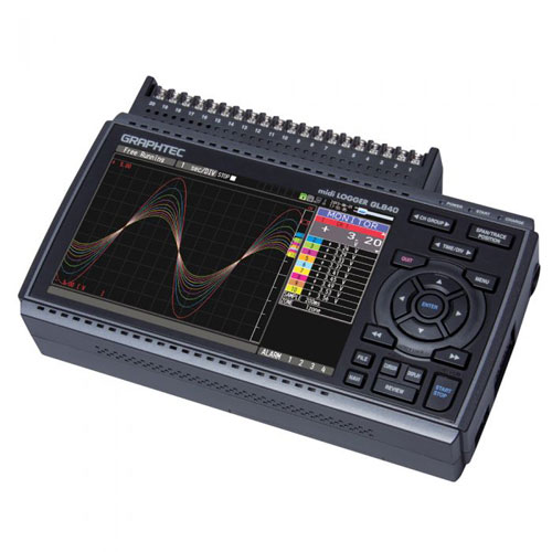
Overview of the Graphtec GL840-M 20-Channel Multifunction Data Logger
The Graphtec GL840-M midi logger is the DAQ device you need for small to large-scale data acquisition applications. 20 isolated input channels for high speed voltage, temperature, logic/pulse inputs, and even humidity (with optional sensor) allow it to be used in many applications. The GL840-M can be expanded up to 200 channels with per-channel programming. The built-in 7-inch color display lets you easily view your data, and with support for up to 32GB of removable SD memory, you can store everything you need to. Use your Graphtec data logger as a standalone device or connect it to a PC for high-speed data acquisition.
User Manuals and Product Guides

Graphtec GL840 Data Logger Specifications
| Number of Channels | 20 Analog Signal Input Channels (Expandable to 200 Channels using Graphtec B-566 and B-564) |
| Analog Input Terminals | Type: Multi-Input Type 1 Analog Input (20 Channels/terminal); Supports up to 10 Terminals |
| Filter | Off, 2, 5, 10, 20, 40 (Moving Average in Selected Number) |
| Input Method | All channels Isolated Balanced Input, Scans channels for sampling |
| Type of Input Terminal | Screw Terminal (M3 Screw) |
| Digital Sensor | 1 port for GL Digital Sensor |
| External Inputs | Trigger or Sampling (1 Channel); Logic/Pulse (4 Channels) |
| External Outputs | Alarm (4 Channels) |
| Input Voltage (Max) | Between (+)/(-) Terminals: 60 Vp-p (20 mV to 2 Volts); 110 Vp-p (5 Volts to 100 Volts) Channels (-)/(-): 60 Vp-p Channel / GND: 60 Vp-p |
| Max Voltage (Withstand) | Between Channels: 350 Vp-p (1 Minute) Channel / GND: 350 Vp-p (1 Minute) |
| Measurement Ranges | Voltage: 20, 50, 100, 200, 500mV; 1, 2, 5, 10, 20, 50V; 1 to 5 Volts FS Thermocouple: Type K, J, E, T, R, S, B, N and W Supported RTD: PT100 (Spec IEC751), JPT100 (Spec JIS), PT1000 (Spec IEC751) Humidity: 0 to 100% (w/ Optional Graphtec B-530 Humidity Sensor) |
| Measurement Accuracy | Voltage: • 0.1% Full Scale Type R Thermocouple: • 0°C ≤ TS ≤ 100°C: ±5.2°C • 100°C < TS ≤ 300°C: ±3.0°C • 300°C < TS ≤ 1600°C: ±(0.05 % of Rdg + 2.0°C) Type S Thermocouple: • 0°C ≤ TS ≤ 100°C: ±5.2°C • 100°C < TS ≤ 300°C: ±3.0°C • 300°C < TS ≤ 1760°C: ±(0.05 % of Rdg + 2.0°C) Type B Thermocouple: • 400°C ≤ TS ≤ 600°C: ±3.5°C • 600°C < TS ≤ 1820°C: ±(0.05% of Rdg + 2.0°C) Type K Thermocouple: • -200°C ≤ TS ≤ -100°C: ±(0.05% of Rdg + 2.0°C) • -100°C < TS ≤ 1370°C: ±(0.05% of Rdg + 1.0°C) Type E Thermocouple: • -200°C ≤ TS ≤ -100°C: ±(0.05% of Rdg + 2.0°C) • -100°C < TS ≤ 800°C: ±(0.05% of Rdg + 1.0°C) Type T Thermocouple: • -200°C ≤ TS ≤ -100°C: ±(0.1% of Rdg + 1.5°C) • -100°C < TS ≤ 400°C: ±(0.1% of Rdg + 0.5°C) Type J Thermocouple: • -200°C ≤ TS ≤ -100°C: ±2.7°C) • -100°C < TS ≤ 100°C: ±1.7°C) • 100°C < TS ≤ 1100°C: ±(0.05% of Rdg + 1.0 °C) Type N Thermocouple: • 0°C ≤ TS ≤ 1300°C: ±(0.1% of Rdg + 1.0°C) Type W Thermocouple: • 0°C ≤ TS ≤ 2000°C: ±(0.1% of Rdg + 1.5°C) Reference Junction Compensation: ±0.5°C Pt100 RTD Sensor: • -200°C ≤ TS ≤ 100°C: ±1.0°C • 100°C < TS ≤ 500°C: ±1.0°C • 500°C < TS ≤ 850°C: ±(0.05 % of Rdg + 2.0°C) JPt100 RTD Sensor: • -200°C ≤ TS ≤ 100°C: ±0.8°C • 100°C < TS ≤ 500°C: ±0.8°C Pt1000 RTD Sensor: • -200°C ≤ TS ≤ 100°C: ±0.8°C • 100°C < TS ≤ 500°C: ±0.8°C |
| Sampling Interval | Voltage: 10ms (1 Channel), 20ms (2 Channels), 50ms (5 Channels), 100ms (10 Channels) 200ms-1 Hour (All Channels) Temperature: 100ms (10 Channels) 200ms-1 Hour(All Channels) |
| Time Scale of Waveform Display | 1 second to 24 Hour/Division |
| Trigger, Alarm Function | Trigger Action: • Start or Stop Capturing Data by the Trigger Repeat Action: • Off, On (Auto Rearmed) Trigger Source: • Start: Off, Measured Signal, Alarm, External, Clock, Week or Time • Stop: Off, Measured Signal, Alarm, External, Clock, Week or Time Combination: • OR or AND Condition at Level of Signal or Edge of Signal Condition Setting: • Analog: Rising, Falling, Window-in, Window-out • Pulse: (High), Falling (Low), Window-in, Window-out • Logic Signal: Pattern (Combination of Each Input Signal in High or Low) Alarm Output: • Outputs a Signal When Alarm Condition Occurs in the Input Signal |
| Pulse Input | Accumulating Count Mode: • Number of Pulses from the Start of Measurement • Range: 50, 500, 5k, 50k, 500k, 5 M, 50 M, 500 M Counts/FS Instant Count Mode: • Counting the Number of Pulses per Sampling Interval • Range: 50, 500, 5k, 50k, 500k, 5 M, 50 M, 500 M Counts/FS Rotation Count (RPM) Mode: • Counting the Number of Pulses per second then Convert to RPM (Rotations per Minute) • Range: 50, 500, 5k, 50k, 500k, 5 M, 50 M, 500 M Counts/FS |
| Calculation Function | Between Channels: Addition, Subtraction, Multiplication and Division for Analog Inputs Statistical: Select 2 Calculations from Average, Peak, Maximum, Minimum and RMS |
| Search Function | Search for Analog Signal Levels, Values of Logic or Pulse or Alarm Point in Captured Data |
| Interface to PC | Ethernet (10 Base-T/100 Base-Tx), USB (Hi-Speed), WLAN (using Graphtec B-568 Wireless Lan Adapter) |
| Storage Capacity | Internal Storage: 4GB Media: SD Memory Card (SDHC up to 32GB) Saved Contents: Captured Data, Setting Conditions, Screen Copy |
| Capturing Mode | Mode: Normal, Ring, Relay Ring: Saves Most Recent Data (1,000 to 2 Million Readings) Relay: Saves Data to Multiple Files without losing data until Data Capturing is Stopped |
| Replay Data | Replays Captured Data That Was Saved (BGD or CSV Format) |
| Scaling Engineering Unit Function | Set Based on the Reference Point of the Scaled Output and Input Signal for Each Channel Analog Voltage: Converts using 4 Reference Points (Gain, Offset) Temperature: Converts using 2 Reference Points (Offset) Pulse Count: Converts using 2 Reference Points (Gain) |
| Display | Size: 7.0" TFT Color LCD (WVGA: 800 x 480 pixels) Language: English, French, German, Chinese, Korean, Russian, Spanish and Japanese Information: Waveform in Y-T with Digital Values, Waveform Only, Digital Value, Digital Values and Statistics Values |
| Action During Data Capture | Displaying past data (using Dual Display Mode - Current + Past Data) Hot-swapping the SD Memory Card Saving Data in Between Cursors |
| Power Source | AC Adapter: 100 to 240 Volts AC, 50/60 Hz (1 pc of Adapter is Attached as Standard Accessory) DC Power: 8.5 to 24 Volts DC (Graphtec B-514 DC Power Cable is Required) Battery Pack: Mountable Battery Pack - 7.2 Volts DC, 2900mAh (Requires Graphtec B-569 Battery Pack) |
| Power Consumption | Max. 38 VA |
| A/D Converter | ΣΔ Type; 16 Bits (Effective Resolution: 1/40,000 of Full Range) |
| Operating Environment | Temperature: 0 to 45°C Humidity: 5 to 85% RH (Non-condensing) |
| OS Compatibility | Windows 11, 10 and 7 (32 and 64 Bit) |
| Weight | 1010 grams (35.63 ounces) |
| Dimensions | 240mm x 158mm x 52.5mm (Excluding Protrusions) |


Customer Questions
Related Products


