USB-1808 8 Channel 18-Bit Data Acquisition USB DAQ Module
Measurement Computing Data Acquistion Module with 18-Bit Analog Inputs and 50 kS/s Sampling Rate
SKU
USB-1808
$769.00
- (8) 18-Bit Analog Inputs, (2) Analog Outputs, (4) Digital I/Os, (2) Counters, (2) Quadrature Encoders and (2) Timer Outputs
- Simultaneous Samplling up to 50 kS/s Per Channel
- Synchronous Operations (Read Analog, Digital and Counter Inputs and Generate Analog and Digital Outputs Simultaneously)
- External Clock I/O, External Digital Triggering and Pattern Triggering
- Powered by USB Port on your Computer, External Power Not Required.
Includes USB Cable and Measurement Computing DAQ Software Suite (DAQami, TracerDAQ, InstaCal, Universal Libraries for Windows, Android and NI LabVIEW) Available as a Download
Due to product shortages lead times on most Measurement Computing orders will range from 7-16 weeks.
Overview of the Measurement Computing USB-1808 Data Acquisition DAQ
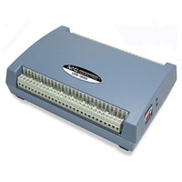
The Measurement Computing USB-1808 data acquisition DAQ device provides simultaneous sampling with eight 18-bit analog inputs, 2 x analog outputs, 4 x digital I/Os, two 32-bit counters and encoders and 2 x timer outputs. The USB-1808 can sample simultaneously at up to 50 kS/s per channel.
Software Downloads


Product Videos

User Manuals and Product Guides

(Size: 0.01 MB)
This Document is Required to be Filled out by Anyone Outside the United States Purchasing a Measurement Computing Product.
Measurement Computing USB-1808 DAQ Module Specifications
| Analog Input | Number of Channels: 8 Differential, 8 Single-Ended - Software Selectable A/D Converter Type: Simultaneous ADC Resolution: 18 Bits Input Voltage Range: ±10 Volts, ±5 Volts, 0V to 10 Volts, 0 Volts to 5 Volts (Note: Software Selectable Per-Channel) Input Impedance: >1 GΩ (Power On); 1000 Ω (Power Off) Sample Rate: 0.023 Hz to 50 kHz (Software Selectable) Trigger Source: ITRIG and Digital Pattern Detection Channel Gain Queue: Up to 8 Elements, 8 Element Per Unique, consecutive channels paired with any valid range; Software-Selectable |
| Analog Output | Number of Channels: 2 Resolution: 16 Bits Output Ranges (calibrated): ±10 Volts Output Current: ±3.5mA Max Output Coupling: DC Output Noise: 100 µVrms Trigger Source: OTRIG and Digital Pattern Detection Scan Clock Source: Internal Output Scan Clock or External Output Scan Clock Output Update Rate: 0.023 Hz to 125 kHz per Channel Slew Rate: 15 V/µS Throughput (Software Paced): 33 S/s to 8,000 S/s typical, system-dependent Throughput (Hardware Paced): 250 kS/s max, system-dependent |
| Digital Input/Output | Digital Type: CMOS Number of I/O: 4 Configuration: Independently Configured for Input or Output Input High Voltage: 2.0 Volts Min, 5.5 Volts Absolute Max Input Low Voltage: 0.8 Volts Max, -0.5 Volts Absolute Min Output High Voltage: 4.4 Volts Min (IOH = -50 µA); 3.76 Volts Min (IOH = -2.5 mA) Output Low Voltage: 0.1 Volts Max (IOL = 50 µA); 0.44 Volts Max (IOL = 2.5 mA) Output Current: ±2.5mA Max |
| Quadrature Inputs | Terminal Name: ENC0A, ENC0B, ENC0Z, ENC1A, ENC1A, ENC1Z Number of Encoders: 2 Signals per Encoder: A, B and Z Resolution: 20 ns Maximum Frequency: 50 MHz Minimum Pulse Width: 10 ns De-Bounce Function: None Scan Clock Source: Internal Input Scan Clock or External Input Scan Clock (ICKK1 pin) Trigger Source: ITRIG and Digital Pattern Detection Input High Voltage: 2.2 Volts Min; 5.5 Volts Max Input Low Voltage: 1.5 Volts Max; -0.5 Volts Min Absolute Maximum Input Voltage: 5.5 Volts |
| Timer | Terminal Name: TMR0 and TMR1 Timer Type: PWM Output with Count, Period, Delay and Pulse Width Registers Output Value: Default State is Idle Low with Pulses High, Software-Selectable Output Invert Internal Clock Frequency: 100 MHz Register Widths: 32-Bit Pulse Width: 10 ns Min (High and Low) Output High Voltage: 4.4 Volts Min (IOH = -50 µA); 3.76 Volts Min (IOH = -2.5 mA) Output Low Voltage: 0.1 Volts Max (IOL = 50 µA); 0.44 Volts Max (IOL = 2.5 mA) Output Current: ±2.5 mA Max |
| External Trigger | Trigger Source: ITRIG (Inputs), OTRIG (Outputs) Trigger Mode: Software Programmable for Edge ot Level Sensitive, Rising or Falling Edge, High or Low Level. Power on Default is Edge Sensitive, Rising Edge. Trigger Latency: 1µs + 1 Clock Cycle Max Trigger Pulse Width: 100 ns Min Input Type: Schmitt Trigger, 33 &Omega Series Resistor and 49.9 kΩ Pull-Down to Ground Schmitt Trigger Hysteresis: 0.4 Volts to 1.2 Volts Input High Voltage: 2.2 Volts (Min); 5.5 Volts (Absolute Max) Input Low Voltage: 1.5 Volts (Max); -0.5 Volts (Absolute Min); 0 Volts Recommended Min. |
| Pattern Trigger | Trigger Source: DIO0 to DIO3 Trigger Types: Above Pattern, Below Pattern, Equal Pattern, or Not Equal Pattern Trigger Stability: Digital Port must be Stable for 50 ns to be Recognized as a Pattern Trigger Bit Width: Up to 4, Adjustable through Bitmask Trigger Latency: Up to 1 Scan Period |
| External Clock Input/Output | Terminal Names: ICLKI, ICKLO, OCLKI, OCLKO Input Clock Rate: 125 kHz Max Clock Pulse Width: 400 ns min (xCLKI and xCLKO) Input Type: Schmitt Trigger, 33 &Omega Series Resistor, 47 kΩ Pull-Down to Ground Schmitt Trigger Hysteresis: 0.4 Volts to 1.2 Volts Input High Voltage: 2.2 Volts (Min); 5.5 Volts (Absolute Max) Input Low Voltage: 1.5 Volts (Max); -0.5 Volts (Absolute Min); 0 Volts Recommended Min Output High Voltage: 4.4 Volts Min (IOH = -50 µA); 3.76 Volts Min (IOH = -24 mA) Output Low Voltage: 0.1 Volts Max (IOL = 50 µA); 0.44 Volts Max (IOL = 24 mA) Output Current: ±2.5 mA Max |
| Counter | Counter Type: FPGA Number of Channels: 2 Resolution: 32 Bits Input Frequency: 50 MHz Max Input Type: Schmitt Trigger, 33 &Omega Series Resistor, 47 kΩ Pull-Down to Ground Schmitt Trigger Hysteresis: 0.76 Volts Typical, 0.4 Volts (Min); 1.2 Volts (Max) Input High Voltage Threshold: 1.74 Volts typical, 1.3 Volts (Min); 2.2 Volts (Max) Input Low Voltage Threshold: 0.98 Volts typical, 0.6 Volts (Min); 1.5 Volts (Max) Input Low Voltage Limit: -0.5 Volts Absolute Min; 0 Volts Recommended Pulse Width: 20 ns, 200 ns, 2 µs or 20 µs (Software Selectable) Trigger Source: ITRIG and Digital Pattern Detection Counter Read Clock: Internal or Exernal Input Scan Clock up to 200 kHz |
| USB Communications | Type: USB 2.0 High-Speed Compatibility: USB 1.1, USB 2.0 and USB 3.0 Cable Length: 3 Meters Max |
| Power Source | BUS Powered |
| Operating Range | Temperature: 0° to 55°C Humidity: 0 to 90% RH Non-Condensing Max |
| Storage Range | Temperature: -40°C to 85°C Humidity: 0 to 90% RH Non-Condensing Max |
| OS Compatibility | Windows 11, 10 and 7 (32 or 64-Bit) for Universal Library, LabView |
| Software Support | DAQami, TracerDAQ Pro, DASYLab, LavView and Universal Library |
| Dimensions | 127mm x 89.9mm x 35.6mm (5.00" x 3.53" x 1.40") |
Customer Questions
Related Products
