16-Channel Multifunction Data Logger w/ 200 kS/s Sampling Rate
Measurement Computing Logger with 500 Volts DC Isolation on 16 Digital Inputs and 4 Counter Channels
SKU
LGR-5329
$2,540.00
- (16) Single-Ended Analog Inputs, (16) Isolated Digital Inputs and (4) Quadrature Counter Inputs
- ±1 Volt, ±5 Volts, ±10 Volts and ±30 Volts Analog Input Measurement Ranges
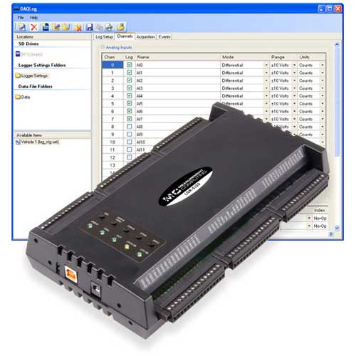
- SD Card for Data Storage and Loading Configuration Data onto Logger
- 500 Volt DC Isolation Between All Analog, Digital Inputs and the Host PC
- Powered by 9 to 30 Volt External Power Adapter
Includes AC Power Adapter, USB Cable, 4 GB SD Card and DAQLog Software
Due to product shortages lead times on most Measurement Computing orders will range from 7-16 weeks.
User Manuals and Product Guides

(Size: 0.01 MB)
This Document is Required to be Filled out by Anyone Outside the United States Purchasing a Measurement Computing Product.
Measurement Computing LGR-5329 16 Channel Multifunction Data Logger Specifications
| Logging Rate | 200 kHz (Maximum) | |
| Mechanical Shock | Operating: 50 g, 3 msec half sine; 30 g, 11 msec half sine; 3 hits per face for a total of 18 hits (18 hits at 50 g, 18 hits at 30 g) Standard: IEC 60068-2-27 |
|
| Random Vibration | Frequency: 10 to 500 Hz Vibration Level: 5 grms Test Time: 100 Minutes/axis Standard: IEC 60068-2-64 |
|
| Memory Card | Type: SD Memory Card Storage Capacity: 32 GB (Max) 4GB SD Memory Card Included |
|
| One Touch Logging Controls |
Configuration Loading from SD Memory Card Start/Stop Logging Force Trigger/User Event Device Reset Control of Status LEDs |
|
| LEDs | Instant Logging Tigger Status Activity State |
|
| Power | 9 Volt to 30 Volt External Power Supply | |
| Operating Range | Temperature: 0 to 55°C Humidity: 0 to 90% non-condensing |
|
| Storage Range | Temperature: -40 to 85°C Humidity: 0 to 90% non-condensing |
|
| OS Compatibility | Windows 11, 10 and 7 (32 and 64-Bit) | |
| Dimensions | 241.30mm x 127mm x 44.50mm (9.5" x 5.0" x 1.75") | |
| Counters | Type: Quadrature and Conventional (x1, x2, x4) Channels: 4 Inputs: Phase A=/A-, Phase B+/B-, Index ± Resolution: Fixed 32-bit or as Sized by Modulo Register Count Modes: Quadrature, Up/Down, Period/Frequency, Modulon De-Bounce Times (Programmable): 16 Steps from 500 ns to 25 ms; positive or negative edge sensitive; glitch detect mode or de-bounce mode Time-Base Accuracy: 50 ppm Receiver Type: Quad Differential Receiver Configuration: Each Channel Consists of Phase A input, Phase B input and Index input; each input switch selectable as single-ended or differential Differential: Phase A, Phase B and Index (+) inputs at user connector routed to (=) inputs of differential receiver. Phase A, Phase B and Index (-) inputs at user connector routed to (-) inputs of differential receiver. Single-Ended: Phase A, Phase B and Index (+) inputs at user connector routed to (+) inputs of differential receiver. Phase A, Phase B and Index (-) inputs at user connector routed to ground. (-) Inputs of differential receiver routed to +3 Volt reference Common Mode Input Voltage Range: ±12 Volts Max Differential Input Voltage Range: ±12 Volts Max Input Sensitivity: ±200 mV Input Hystersis: 50 mV typical Input Impedance: 12 kΩ minimum Absolute Maximum Input Voltage: Differential, ±14 Volts Max |
|
| Triggers | Multi-Channel Analog: Level-Sensitive Based on Acquired Data. Up to 16 Channels May be Used as Independant Trigger Sources Digital Pattern Trigger: Trigger when a User-defined 1 to 16 Bit digital pattern is matched on the DIN0-DIN15 pins. Programmable mask bits. Non-Pretrigger Acquisition: 100 ns Typical, 1µs max Pretrigger Acquisition: 1 Scan Period Max External Trigger Pulse Width: 1µs min Internal Trigger Latency: 2 (1/per-channel Sample Rate) |
|
| Analog Input | ||
|---|---|---|
| A/D Converters | 16-Bit Successive Approximation Type | |
| Number of Channels | 8 Differential/16 Single-Ended | |
| Input Ranges | ±1 Volts, ±5 Volts, ±10 Volts and ±30 Volts | |
| Input Configuration | Multiplexed | |
| Absolute Max Input Voltage | CH_x to AGND, ±38 Volt Max (Power ON/OFF) | |
| Input Impedance | 30 Volt Range: 1 MΩ (Power ON); 1GΩ (Power OFF) All Other Ranges: 10 GΩ (Power ON); 1GΩ (Power OFF) |
|
| Input Leakage Current | ±100 pA | |
| Input Capacitance | 30 Volt Range: 90 pf 10, 5, 1 Volt Range: 55 pf |
|
| Max Working Voltage | Signal+Common Mode 30 Volt Range: ±30.05 Volts 10, 5, 1 Volt Range: ±10.2 Volts |
|
| Common Mode Rejection Ratio | 30 Volt Range: 65 db min (fin=60 Hz) All Other Ranges: 75 dB min (fin=60 Hz) |
|
| Crosstalk | DC to 25 kHz, Adjacent Differential Mode Channels, -80 dB | |
| ADC Resolution | 16 Bits | |
| Input Bandwidth | 450 kHz Min (All Input Ranges) | |
| Input Coupling | DC | |
| Warm-up Time | 30 Minutes Minimum | |
| Absolute Accuracy | 0.07% FSR (All Ranges) | |
| Noise | 2 LSB rms (Differential Mode) | |
| Digital Input | ||
| Input Type | Industrial | |
| Input Voltage Range | 0 to 30 Volts | |
| Input Characteristics | Resistor Divider 39.2 kΩ Series Resistor and 10 kΩ Shunt Resistor Connected to IGND | |
| Max Input Voltage Level | 0 to 36 Volts (Power ON/OFF) | |
| Input Voltage Threshold | Minimum High Level: 10.04 Volts Max Maximum Low Level: 3.85 Volts Minimum |
|
| Event Logging | Change of State, Pattern Recognition, Event Time Stamped Using Real Time Clock | |
| Isolation | 500 Volts DC Minimum | |
| Digital Output | ||
| Number of Outputs | 1 | |
| Type | Mechanical Relay, NEC ED2/EF2 Series | |
| Relay Contact | Configuration: 1 Form C Resistance: 0.075 Ω Operate Time: 3 mS (Excluding Bounce) Release Time: 2 mS (Excluding Bounce) Insulation Resistance: 1000 MΩ at 500 VDC Switching Voltage: 220 Volts DC/250 Volts AC Switching Current: 1.0 Amps Carrying Current: 2.0 Amps |
|
Customer Questions